Weatherby German MK V Trigger Housing
Right Hand version shown below
This trigger/safety unit was used on the early German MK V’s & the original was made of a Zinc die casting that over time seemed to self destruct. Later ones were fitted with the safety lever mounted on the left side of the bolt sleeve. If the Zinc housing became broken, (which was common) the only alternative was to replace the complete trigger unit with the newer Japanese or American trigger units, PLUS the bolt sleeve with the newer safety & the striker, creating a rather expensive repair.
As of 2018, Wisner’s Inc is no longer making this replacement trigger housing, we do not know of a source for a new housing
We will not go into how to take the unit apart. But, we will share with you what we have found about replacing the housing & what pins, springs etc. &where they go, as over time & unknown gunsmithing, parts may be misplaced.
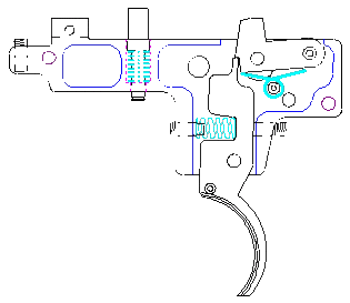
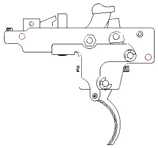
We are supplying replacement roll pins & “E” clips as we found that some of the pins may be bent & surely the clips may be missing or seem to disappear in thin air when you try to reassemble the unit. We have also made some slight design changes, namely the replacement of the safety plunger pin & “E” clip with a machine bolt& an aircraft type lock nut. In the illustration on the left above, you will notice the relationship of the various parts.
There are 2 lighter weight coil springs; these are the same size & length, they are for the bolt stop & the safety detent ball unit. The heavier & slightly shorter coil spring is the trigger tension spring. The one heavy wire, double tailed spring is the sear tension spring.
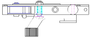
There are (3) 8-40 set screws. One or 2 can be a dog point, if only 1, then it is the trigger tension spring adjustment screw that goes into the front of the trigger housing at the recessed area of the trigger. If there are 2 dog points, the second is used for the trigger engagement adjustment screw on the rear. The other full threaded screw is the trigger housing tension screw on the front of the housing& puts tension up against the receiver to tighten the housing against the receiver.
There are 3, headed 1/8” pins. One has a smaller head, approx .200” while the other 2 are .250”, discard 1 of the .250”.
It is imperative that when you disassemble the old unit that you clean & inspect it thoroughly. Install the set screws in their respective locations. From our kit replace the 3/32” x 3/8 roll pins for the sear & sear spring. Check free movement of the sear on the sear pivot pin. We have found that sometimes the sear spring’s tails do not want to stay in place under the sear. Take a Dremel tool with a 1” dia. cut off wheel & just grind a shallow groove on both the front & rear opposite sides on the under side of the sear, matching the sear spring’s tails. These grooves prevent the tails from sliding off to the sides & possibly bind things up creating a safety issue. Install the sear & the sear spring as described above & as per the above illustration on the left. You will notice that the sear has an 1/8” pin protruding on the RH side. This is for the safety engagement, as the safety lever raises the sear& blocks it’s movement when the safety lever is in the “ON” position.
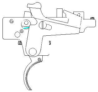
One of the large headed pins goes thru the safety lever PIVOT hole & also into the trigger PIVOT hole of the housing. Install the trigger on this pin from the LH side. Slip the heavy trigger spring into the recess in the front of the trigger& onto the adjustment screw dog point. Adjust the rear adjustment screw so that about ½ of the trigger’s top is engaged. This is about .020 & is adjusted by the rear adjustment screw. Now screw in the front tension screw. The screw’s shoulder contacts the spring to increase the trigger tension. Suggested trigger pull weight is 4 ½#.
Install the sideplate on the 2 locator protrusion pegs, found on the front & rear of the housing. You may have to tap this sideplate on with a small hammer to seat it. The “E” clip can now be placed on Left Hand side of the sideplate on the protruding trigger pin & in it’s groove to help hold the unit together. After final assembly you may want to rivet these machined housing pegs to help retain the sideplate.
Next will come the smaller headed pin, & it goes in from the RH side of the housing thru the 1/8” hole about ½” forward of the rear edge of the unit. This is the pivot for the bolt stop retractor lever. This lever, when laying along side of the trigger housing has a small round hole that goes over a protruding roll pin on the forward LH side of the trigger just below the housing. Place another “E” clip on this pin’s LH side as per the upper LH illustration. Next will be the bolt stop plunger & spring unit. Place one of the lighter weight springs on the shaft of the bolt stop,& insert it into the round hole in the top just rearward of the large locator/retainer lug. The smaller shaft end of the bolt stop also has a small groove that accepts another ”E” clip when it is pressed down enough to go thru the slot in the retractor lever’s bottom forward pad.
Rotate the safety lever forward & down out if the way for the plunger. The final lighter coil spring goes in the .200” dia hole from the Right Hand side of the housing. Next will be the .200” dia. X .150 thick, one end radiused hollow round safety detent plunger. Align the plunger on the spring & depress it against the spring allowing both to be pushed in the housing’s hole & slightly flush with the RH side of the housing. Now while holding the spring & plunger in, rotate the safety lever back into position . Insert our supplied #5 flat steel washer on our also supplied #4 – 40 machine bolt & from the RH side of the housing push it thru the safety lever’s elongated hole, the spring & plunger, allowing the bolt to protrude out the LH sideplate. Install the aircraft type locknut on the LH side. Tighten the nut until it is snug, but still allowing movement of the safety lever. The steel washer under the bolt’s head against the safety lever gives assurance the safety lever operates without binding if you place a drop of oil on it where it does thru the safety lever.
Place the assembled trigger housing unit in the receiver’s round recess, install the retainer cross pin & tighten the forward tension screw to secure the unit in position. Install the bolt assembly& check to see if the bolt stop is functioning.
You can now do a final function check, set the trigger engagement & pull weight if need be. As a final safety check, (WITH AN UNLOADED FIREARM) with the safety lever “back” in the “ON” position, pull the trigger. It SHOULD NOT FIRE. Push the safety lever “forward” to “OFF” & it SHOULD FIRE, when the trigger is pulled. Open & close the bolt, & again with the safety lever “back” in the “ON” position, pull the trigger, let go of the trigger, then push the safety lever “OFF”, it SHOULD NOT FIRE without touching the trigger. Install the barreled action in the stock, check the bolt stop function & for interference anywhere on the trigger system, & do the above safety checks again.
The only difference between the RH & LH versions are that the safety plunger hole in the housing is a different size to accommodate the safety detent. The sideplate detent hole is changed to match the corresponding housing hole with the safety lever & bolt release connector bar are a mirrored part.
If it fails any of these tests, go back & check your installation, or if anyone in the past has altered any part.


